Guides / Applications
Ceramic Insulators for Vacuum Feedthroughs: Material, Seal and Leak Rate
October 11, 2026
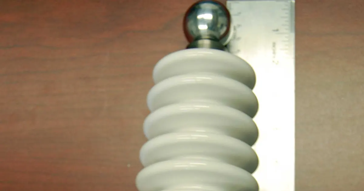
A vacuum feedthrough carries power, a signal or a fluid line through the wall of a vacuum chamber without letting air in. The insulating part, almost always a ceramic, does two jobs at once. It keeps the conductor electrically separate from the chamber wall, and it forms a leak-tight seal between the conductor and the wall.
Doing both well takes a dense ceramic, a sound ceramic to metal joint and a drawing that states the leak rate, the voltage and the bakeout in numbers.
What the insulator must do
- Hold off voltage. The ceramic body and the path along its surface must withstand the working voltage without breakdown or flashover.
- Stay gas tight. There must be no open porosity through the wall and no leak at the seal.
- Release little gas. In ultra high vacuum, the ceramic should not give off water or other gas as it warms.
- Survive bakeout. Chambers are heated for many hours to drive off water, so every joint must tolerate repeated cycles.
- Stay clean. Surface contamination or particles can ruin a high voltage hold-off or a clean process.
Choosing the ceramic
| Material | Reasons to choose it | Limits |
|---|---|---|
| Alumina 94 to 96 percent | Low cost, well proven metallising routes | Some glassy phase, lower purity |
| Alumina 99.5 percent | Higher purity, lower loss, cleaner surface | Higher cost |
| Forsterite | Expansion close to many metals, very low loss | Weaker in thermal shock, lower strength |
| Aluminium nitride | High thermal conductivity for heat carrying leads | Higher cost, needs its own metallising process |
| Sapphire | Optical access and clean single crystal | High cost, cleavage |
| Machinable glass ceramic | Fast prototypes, complex shapes | Weaker, lower temperature limit |
For the full comparison between steatite and forsterite and where each fits, see steatite and forsterite for electrical insulators. For the purity trade-off in alumina, read which alumina purity do you need.
Dense alumina absorbs essentially no water and has no open porosity, which is why it is the usual body for a vacuum seal. A porous insulator would let gas creep through the wall and trap moisture.
The seal: ceramic to metal
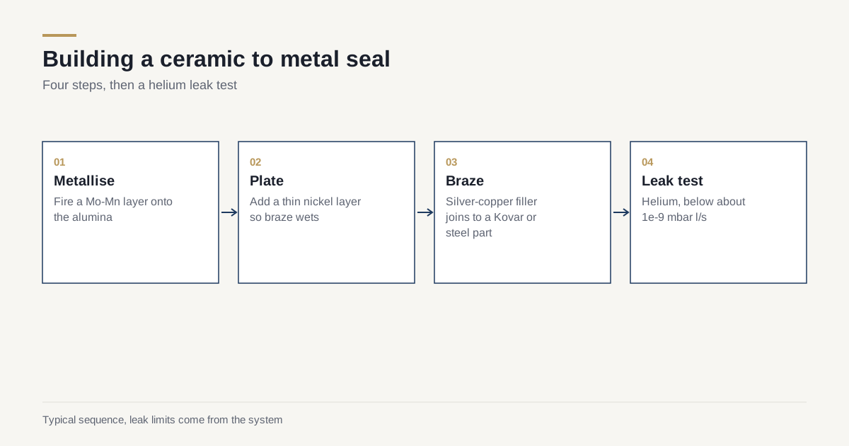
The ceramic cannot be welded, so a metal layer is built onto it first.
- Metallising. A paste, often molybdenum and manganese, is fired onto the ceramic surface. The paste bonds to the ceramic at high temperature.
- Plating. A thin nickel layer goes over the metallisation so that braze wets it.
- Brazing. A filler metal, often a silver-copper eutectic, melts at under about 800 degrees C and joins the metallised ceramic to a metal part such as a Kovar sleeve or a stainless flange.
- Cooling. The joint cools. Expansion differences between ceramic and metal create stress, which is why the metal is selected to match.
Metals used as the mating part often include iron-nickel-cobalt alloys, which expand about as little as alumina, and titanium, which is a close match in some cases. A mismatch leaves stress in the joint and can crack the ceramic or open the seal. The details are in metallising and brazing ceramic to metal.
Leak rate
Leak rate is the main acceptance test. A helium leak detector measures how much helium passes through the part into a vacuum.
- Typical high vacuum parts: a leak rate below about 1 x 10^-9 mbar l/s.
- Ultra high vacuum parts: 1 x 10^-10 mbar l/s or better.
The figure belongs on the drawing together with the test method and the pressure difference. A part that passes at room temperature can leak after thermal cycling, so some buyers add a bakeout and a retest. For general information about measurement and records, read how ceramic parts are inspected.
Voltage, creepage and the shape of the ceramic
Alumina has high dielectric strength in the bulk; datasheets for dense alumina typically quote values in the range of several to over ten kV per millimetre for thin sections, depending on grade and test method, so use the figure on the datasheet for your grade. In practice, the weak path is the surface, along which a spark can creep, especially in poor vacuum or on a contaminated surface. Designers add:
- Longer surface path. Grooves or ribs, called sheds or corrugations, lengthen the creep path without lengthening the part.
- Smooth surfaces. A rough surface holds contamination and starts discharges.
- Shielding of the triple junction. The point where ceramic, metal and vacuum meet concentrates the electric field. Careful shaping of the metal and a small recess reduce it.
- Clean handling. A fingerprint can lower hold-off in a high voltage part.
State the working voltage, the test voltage and whether the part sees DC, AC or pulses.
Bakeout and outgassing
A system is baked to remove water from the walls. The ceramic must tolerate the temperature and cycles. Metallised and brazed joints made with silver-copper braze commonly tolerate bakeout at several hundred degrees Celsius. Epoxy seals often limit the temperature to well below that. State the bakeout temperature and the number of cycles.
Dense alumina releases little gas once it has been baked. Porous ceramics, unglazed steatite and boron nitride release more water and need longer bakeout. For that reason, machinable boron nitride and similar materials need a dry bake before installation.
Types of feedthrough and what each asks of the ceramic
Feedthrough designs vary, and the ceramic does a slightly different job in each.
- Single pin or conductor. A small alumina tube or disc carries one conductor. Easy to make, easy to leak test, and a good starting point for a standard seal.
- Multi-pin. Many pins pass through one ceramic plate. Pin pitch, hole position and hole size tolerance matter, because the metallising must reach each hole wall evenly. Drilling many fine holes in a fired ceramic is slow, so these parts are often formed with the holes in place and ground afterwards. See holes, slots and threads in ceramic.
- High voltage. Larger bodies with grooved surfaces and shaped metal ends to control the electric field.
- Thermocouple. Small ceramic bodies that carry dissimilar metal wires through the wall, where temperature and chemical resistance of the leads also matter.
- Coaxial and RF. The ceramic sets the line impedance through its dielectric constant, so the grade and the dimensions must be held tightly.
- Viewport. A sapphire or glass disc sealed into a metal ring. The same principles apply, with optical quality added.
A worked example
A research group builds an ultra high vacuum chamber that will be baked at 250 degrees C for two days and run at 5 kV on an electrode. They need a high voltage feedthrough with a 10 mm conductor. The drawing asks for 99.5 percent alumina, a grooved body for the creep distance, Kovar end sleeves brazed with silver-copper, a leak rate below 1 x 10^-10 mbar l/s and a clean packing. The first shop quotes a standard 96 percent part with a plain cylindrical body and a leak rate of 1 x 10^-9. The difference is not trivial: the standard part is cheaper but would flash over above 3 kV in their geometry and would not meet the leak requirement after bakeout. The shop that read the drawing, rather than the headline price, proposed the right part. A clear drawing makes quotes comparable. See comparing ceramic quotes.
Common faults
- Cracked ceramic after brazing from an expansion mismatch or an uneven joint.
- Leaks after thermal cycling from fatigue in the braze or the metallisation.
- Surface flashover from contamination, poor shaping or a rough finish.
- Virtual leaks from trapped volumes, such as a blind hole or a gap in the assembly that slowly releases gas.
- Leaks through porous ceramic where the wrong grade was used.
Checklist for the RFQ
- Ceramic grade and purity.
- Maximum voltage, type and test voltage.
- Helium leak rate, with the test method.
- Bakeout temperature and number of cycles.
- Mating metal and the joint design, including a drawing of the metal parts.
- Surface finish and cleanliness requirement.
- Packaging, since clean bags and low contamination matter in UHV.
- Quantity and delivery.
To find shops that supply metallised and brazed ceramic parts, send the drawing and the leak requirement through the RFQ page.
Frequently asked questions
Which ceramic is used for vacuum feedthrough insulators?
High purity alumina, usually 94 to 99.5 percent, is the standard because it is dense, gas tight and insulates well. Forsterite, sapphire and aluminium nitride appear where expansion match, optical access or heat flow decide the choice.
What leak rate should a ceramic to metal seal reach?
A helium leak rate below about 1 x 10^-9 mbar l/s is a common specification for high vacuum feedthroughs, and ultra high vacuum parts often ask for 1 x 10^-10 or better. The figure on your drawing should come from the system requirement.
Can a feedthrough be baked at high temperature?
Yes, within the limits of the weakest joint. Brazed alumina to metal seals commonly tolerate bakeout at 250 to 450 degrees C, but adhesives and elastomers in the design usually set a lower limit. State the bakeout temperature on the drawing.
Need a quote for this part?
Send the drawing. We match you with up to 3 shops that grind this grade and reply within 24 business hours.
Get matched with a ceramic shop